MAKING IR SWITCH
INTRODUCTION:-
Home automation or smart home(also known as domotics) is building automation for the home. It involves the control and automation of lighting, heating (such as smart thermostats), ventilation, air conditioning (HVAC), and security, as well as home appliances such as washer/dryers, ovens or refrigerators/freezers. Wi-Fi is often used for remote monitoring and control. Home devices, when remotely monitored and controlled via the Internet, are an important constituent of the Internet of Things. Modern systems generally consist of switches and sensors connected to a central hub sometimes called a "gateway" from which the system is controlled with a user interface that is interacted either with a wall-mounted terminal, mobile phone software, tablet computer or a web interface, often but not always via Internet cloud services.
While there are many competing vendors, there are very few worldwide accepted industry standards and the smart home space is heavily fragmented.Popular communications protocol for products include X10, Ethernet, RS-485, 6LoWPAN, Bluetooth LE (BLE), ZigBee and Z-Wave, or other proprietary protocols all of which are incompatible with each other.Manufacturers often prevent independent implementations by withholding documentation and by litigation.
ABOUT IR CIRCUIT:-
The circuit diagram below is mostly the same. It uses a TSOP1738 IR receiver module at the input side to receive the 38 KHz frequency IR pulses from the remote control. Under normal condition, the output pin of the IR module is at logic High, which means the transistor T1 (BC557 PNP) is cut-off and its collector terminal is at logic Low. The collector of T1 drives the clock line of the CD4017 decade counter.

IR SANSER

TRANSISTORS

RESISTORS
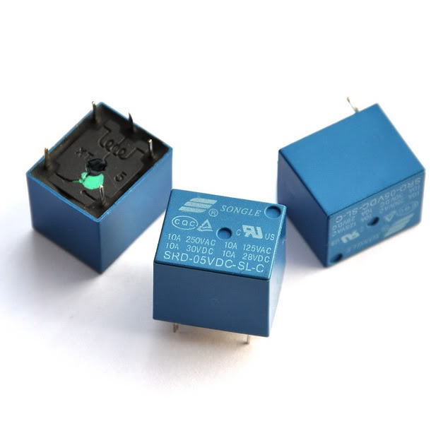
RELAY
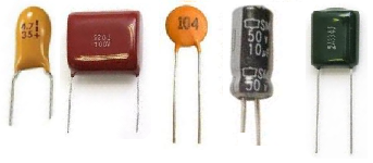
CAPASITORS

CONNECTORS


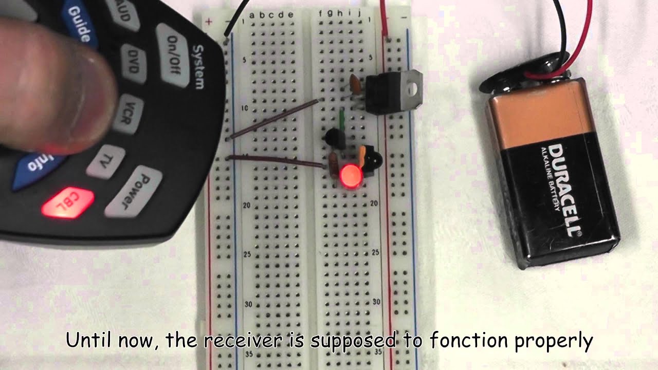
IN BREAD BOARD


Home automation or smart home(also known as domotics) is building automation for the home. It involves the control and automation of lighting, heating (such as smart thermostats), ventilation, air conditioning (HVAC), and security, as well as home appliances such as washer/dryers, ovens or refrigerators/freezers. Wi-Fi is often used for remote monitoring and control. Home devices, when remotely monitored and controlled via the Internet, are an important constituent of the Internet of Things. Modern systems generally consist of switches and sensors connected to a central hub sometimes called a "gateway" from which the system is controlled with a user interface that is interacted either with a wall-mounted terminal, mobile phone software, tablet computer or a web interface, often but not always via Internet cloud services.
While there are many competing vendors, there are very few worldwide accepted industry standards and the smart home space is heavily fragmented.Popular communications protocol for products include X10, Ethernet, RS-485, 6LoWPAN, Bluetooth LE (BLE), ZigBee and Z-Wave, or other proprietary protocols all of which are incompatible with each other.Manufacturers often prevent independent implementations by withholding documentation and by litigation.
ABOUT IR CIRCUIT:-
The circuit diagram below is mostly the same. It uses a TSOP1738 IR receiver module at the input side to receive the 38 KHz frequency IR pulses from the remote control. Under normal condition, the output pin of the IR module is at logic High, which means the transistor T1 (BC557 PNP) is cut-off and its collector terminal is at logic Low. The collector of T1 drives the clock line of the CD4017 decade counter.
Now lets see what happens when somebody faces a TV or DVD remote towards
the TSOP1738 and presses any key on it. The TSOP 1738 module receives
the train of 38 KHz IR pulses from the remote, that makes its output to
oscillate too. These pulses are inverted at the collector of T1, which
finally go to the clock input of the decade counter. The arriving pulses
could increment the CD4017 counter at the same rate (38 KHz), but
because of the presence of the RC filter circuit (R1 = 100K, C1 = 10 uF)
between the collector and the ground, the train of pulses appear as a
single pulse to the counter. Thus, on each key pressing, the CD4017
counter advances only by a single count. When the user releases the key,
the C1 capacitor discharges through the R1 resistor, and the clock line
is back to zero. So every time the user presses and releases a key on
the remote, the CD4017 counter receives a single pulse at its clock
input.
Materials requirds for IR switch
IR SANSER
TRANSISTORS
RESISTORS
RELAY
CAPASITORS
CONNECTORS
CIRCUIT DIAGRAM OF IR SWITCH

IN BREAD BOARD
I have used material as above circuit :
Sr. No.
|
Material Name
|
Qty.
|
1.
|
IR sensor
|
1
|
2.
|
LED (1 watt)
|
2
|
3.
|
PCB
|
1
|
4.
|
Resistors
|
5
|
5.
|
Transistors
|
2
|
6.
|
Relay- 5 volt
|
1
|
7.
|
IC 1CD 4017
|
1
|
8.
|
Capacitor
|
2
|
9.
|
Wire
|


Comments
Post a Comment